Unique to VWT is its ability to integrate with Membrain allowing both upwind and downwind sail shapes to be analyzed with unprecedented accuracy.
!!!...Virtual wind tunneL...!!!
Models air flow at 100% scale
Virtual Wind Tunnel (VWT), was originally developed jointly by Dartmouth College Thayer School of Engineering and North Sails and is now run by the Stevens Institute of Technology. VWT is the first (and still the only) computer simulator to accurately model wind flow on downwind sails at 100% scale. When first developed, North Sails used the world’s two leading low-speed wind tunnels (The University of Auckland's Twisted Flow Wind Tunnel and Oracle’s IACC Twisted Flow Wind Tunnel) to verify it’s accuracy. The results have given us great confidence that North’s “VWT” predicts results with more accuracy than wind tunnel sail testing of any kind. VWT provides powerful insight into flying sail shape, sail drive, shape stability and ease of trim.
Unique to VWT is its ability to integrate with Membrain allowing both upwind and downwind sail shapes to be analyzed with unprecedented accuracy.
Unique to VWT is its ability to integrate with Membrain allowing both upwind and downwind sail shapes to be analyzed with unprecedented accuracy.
Virtual Wind Tunnel run of a Ker 39 medium jib and main showing detailed analysis of the hull and sailplan interaction
Analysis refining the upper shape of a J2 jib studying air flow around leech. Note that headstay and mast are included in the model.
Pressure coefficients used to refine sail shape on A1 asymmetric spinnaker. Note smooth elliptical pressure profile indicating an efficient distribution of loads.
!!!...Wind tunnel testinG...!!!
North Sails has pioneered modern wind tunnel research for sails using two related-but-separate methods. The first is a traditional low-speed tunnel with a unique twist. The other is virtually amazing.
Twisted Flow Wind Tunnel
The University of Auckland's Twisted Flow Wind Tunnel (TFWT), developed in conjunction with North Sails, was created as a research tool to specifically simulate wind flow over yacht sails. It is the only commercial wind tunnel specifically designed for testing yacht sails. Using unique twisting vanes, the wind tunnel accurately models the gradient wind structure seen by a yacht moving through the water. The Twisted Flow Wind Tunnel has been used extensively by America’s Cup boats, Volvo Ocean Racers, Open 60s teams and other successful racing and cruising projects for over 10 years.
Virtual Wind Tunnel
The Virtual Wind Tunnel is the first (and still the only) computer simulator to accurately model wind flow on downwind sails at 100% scale. When first developed, North Sails used both the University of Auckland's Twisted Flow Wind Tunnel and BMW/Oracle’s ACC) to verify its accuracy. These comparisons and real-world performance have given us confidence that the “VWT” predicts results with more accuracy than typically encountered with wind tunnel sail testing of any kind. In addition to sail forces, the VWT provides insightful information to our designers relative to flying sail shape, sail drive, shape stability and ease of trim.
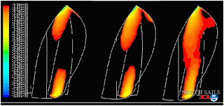
The images below display a sail development process utilizing the VWT to customize a sail shape. The original design on the left was altered based on the predicted flying shape from the pressure’s provided by the VWT and then analyzed with Membrain. The flying shapes and flow images are what allows the designer to know that he is producing a faster, more efficient shape. In this progression from left to right, an increase in efficiency of 2.3% more drive force was realized through this process. Maximizing the low pressure on the leeward side of the sail (more red & orange colors) is what we are after. You can see clearly, the increase represented below.
The images below display a sail development process utilizing the VWT to customize a sail shape. The original design on the left was altered based on the predicted flying shape from the pressure’s provided by the VWT and then analyzed with Membrain. The flying shapes and flow images are what allows the designer to know that he is producing a faster, more efficient shape. In this progression from left to right, an increase in efficiency of 2.3% more drive force was realized through this process. Maximizing the low pressure on the leeward side of the sail (more red & orange colors) is what we are after. You can see clearly, the increase represented below.
!!!...Hull datA...!!!
Uses hull CFD to define hull drag and appendage lift for North VPP
Hull Data one of the most powerful free surface Hydro CFD programs in the world. Hull Data is a Potential Flow, Free Surface Code used for sail and rig develeopent for America’s Cup teams, TP52s and Volvo Ocean Racers. The results from Hull Data are used to generate hydro resistance files for the North Sails VPP.
Hull Data one of the most powerful free surface Hydro CFD programs in the world. Hull Data is a Potential Flow, Free Surface Code used for sail and rig develeopent for America’s Cup teams, TP52s and Volvo Ocean Racers. The results from Hull Data are used to generate hydro resistance files for the North Sails VPP.
Shown ABOVE and BELOW is a hull being run through a series of heel angles to produce a matrix of hull drag to be used in the VPP. In this example, Hull Data is testing a hull at a speed of 5.5 meters/sec., a heel angle of 25 degrees and a yaw angle of 2 degrees.
Subscribe to:
Comments (Atom)


